Hey, Makers!
In the last tutorial, we have gotten some basic ideas on Servo Motor and it’s working! So in this quick tutorial, we are going to Control a Servo Motor with a Potentiometer!

This would really give you a headstart into ServoMotor and Robotics!
Required Materials
1.Any Arduino Board or an Arduino clone board (Buy From Amazon.in)(Buy From Amazon.com)
2.USB cable Type A Male to B Male (Buy From Amazon.in)(Buy From Amazon.com)
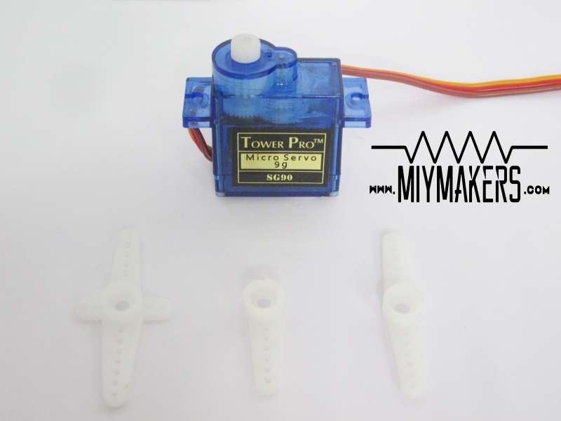
3.Micro Servo SG90 (Buy From Amazon.in)(Buy from Amazon.com)
4.Jumper Wires (Buy From Amazon.in)(Buy from Amazon.com)

How Does it Work?
Before we get started with our Arduino servo Tutorial, when using a motor, always use an external source to power your Arduino, do not draw power from a USB connection!
Servos are controlled by sending an electrical pulse of variable width or pulse width modulation (PWM), through the control wire. Thus it can either be controlled by PWM pins or —any digital pin. As shown in the diagram below, with a 1.5ms pulse width applied to the control line, the servo sits at the neutral position—in this case, identified as 90º. When the pulse width increases or decreases, the servo moves towards 180º or 0º, respectively.You could also describe the neutral position as 0º, in which case the servo’s angular range extends from -90º to +90º.

In other words, a 1.5ms pulse will make the motor turn to the 90° position. A Pulse Shorter than 1.5ms moves it in the anti-clockwise direction toward the 0° position, and any pulse longer than 1.5ms will turn the servo in a clockwise direction toward the 180° position.That’s it!
Schematics
Servo motors have three wires: power, ground, and signal.

1.The power wire is typically red and should be connected to the 5V pin on the Arduino board.
2.The ground wire is typically black or brown and should be connected to a ground pin on the Arduino board.
3.The signal pin is typically yellow, orange or white and should be connected to a digital pin on the Arduino board.
Potentiometer
So, instead of Soldering the Potentiometer to the Jumper Wires, you can also use wires to attach them as in the picture given below! This could surely help you save some Jumper Wires for your future Projects!


Note that servos draw considerable power, so if you need to drive more than one or two, you’ll probably need to power them from a separate supply (i.e. not the +5V pin on your Arduino). Be sure to connect the grounds of the Arduino and external power supply together.
Remember that using the Servo library automatically disables PWM functionality on PWM pins 9 and 10 on the Arduino UNO and similar boards.Thus PWM pin 9 acts as a normal digital pin in our case!
The Code
Arduino IDE has a built-in Servo Code in the Example Code List.
Either you can get the code from the Example Codes or Just download it from the link given below!
[Arduino Ide>File>Examples>Servo>Knob].
Ready To Rock!
Now Run the Code!
As always you can tweak up the code to make your desired changes and make the servo move accordingly! (Guidelines are given in the code)
Do LIKE, SHARE AND SUBSCRIBE to Our Youtube Channel to get Updated with more MIY projects!
Do share us Your Experience via photos and comments in the Comment Section Below! 😀

Nice stuff. Keep it up
LikeLiked by 1 person