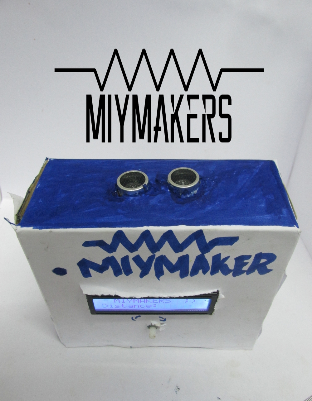
Ever wanted to measure with out a scale or measuring tape?
Measure distance Digitally without a hassle with this small device!
Step 1: HOW IT WORKS?
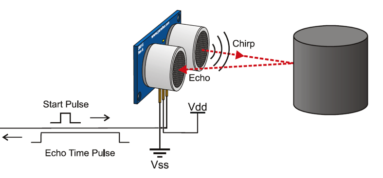
A special sonic transducer is used for the ultrasonic proximity sensors, which allows for alternate transmission and reception of sound waves. The sonic waves emitted by the transducer are reflected by an object and received back in the transducer. After having emitted the sound waves, the ultrasonic sensor will switch to receive mode. The time elapsed between emitting and receiving is proportional to the distance of the object from the sensor.
Step 2: COMPONENTS
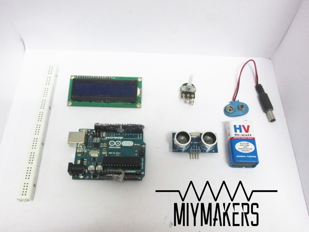
>ARDUINO UNO (Buy From Amazon.in) (Buy From Amazon.com)
>ULTRASONIC SENSOR HC-SR04
(Buy From Amazon)(Buy it from Amazon.com)
>16*2 LCD SCREEN (Buy From Amazon.in)(Buy it From Amazon.com)
>POTENTIO METER [ADJUSTING CONTRAST OF LCD]
(Buy from Amazon.in)(Buy it From Amazon.com)
>9V BATTREY (Buy from Amazon.in)(Buy it From Amazon.com)
>CONNECTION CABLE (Buy from Amazon.in) (Buy it from Amazon)
> Header Pin [optional] (Buy from Amazon.in) (Buy it From Amazon.com)
> Glue Gun [optional](Buy from Amazon.in) (Buy it From Amazon.com)
Step 3: HEADER PIN


Use header pin so that You can easely make this project using only MALE TO FEMALE & FEMALE TO FEMALE JUMPER WIRES
Step 1: Place the Header Pin into the pins of Arduino After it glueing it will look like this.
Step 2:Using GlueGun, Glue the header pin to Arduino so that it does’nt become loose.
Double check whether the header pins are not loose,otherwise there will be no output from the pin!!
Step 4: CIRCUIT
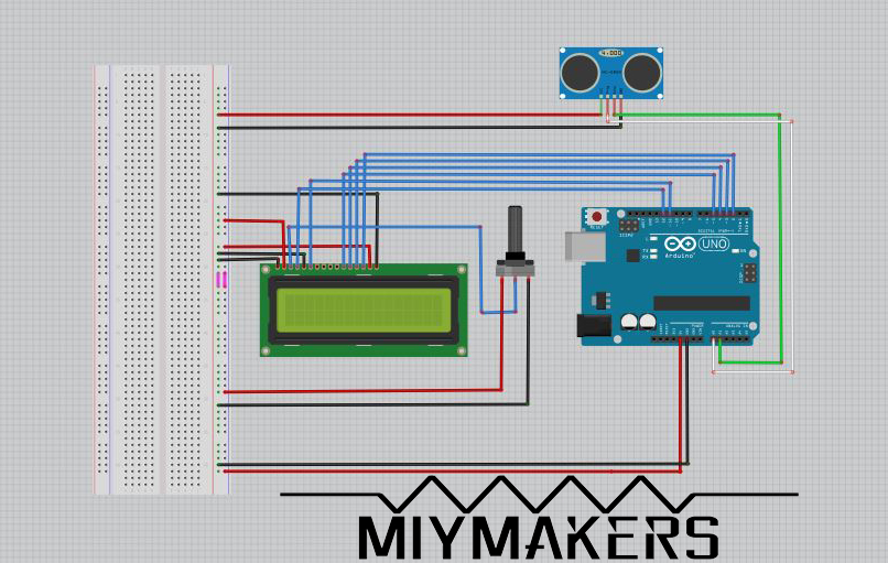
CONNECT ARDUINO ACCORDINGLY!
LCD Connection
D7- DIGITAL PIN 2
D6 – 3
D5 – 4
D4 – 5
E – 11
RS – 12
VDD (+) RAIL BREADBOARD
A (+)RAIL BREADBOARD
—————————————
VSS (-)RAIL BREADBOARD
K (-)RAIL BREADBOARD
RW (-)RAIL BREADBOARD
Step 5: THE BOX
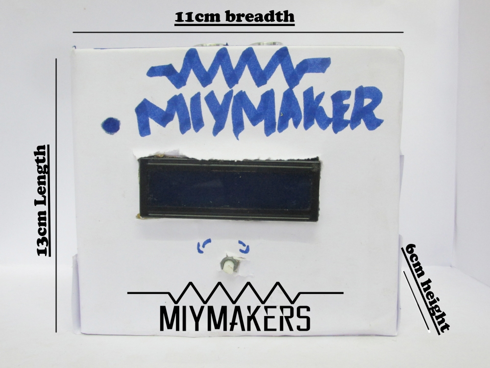
USE A BOX OF MEASURE MORE THAN
13 CM LENGTH
11 CM BREADTH
6 CM HIGHT
USE A BOX OF MORE LENGTH or else everything will be a little messy! (as in the box) 😀
Step 6: MAKE HOLES
MAKE HOLES FOR THE
>>ULTRASONIC SENSOR
>>LCD SCREEN
>>POTENTIOMETER
STICK EVERYTHING USING A DOUBLE SIDE CELLOTAPE


Step 7: KEEP EVRYTHING INSIDE THE BOX!
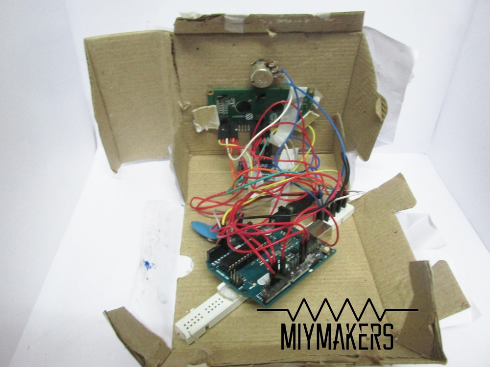
AS I HAD CHOOSEN A SMALL BOX EVERYTHING SEEMS A LITTLE MESSY!
BE SURE TO TAKE A BIG ONE!
Use a 9V battrey/Powerbank to power the arduino
TIP : Cover the box with some colour paper / paint it
Step 8: DATASHEET
DATASHEET
Please download the ULTRASONIC SENSOR library from the above link.
Then Open Arduino IDE Go to Sketch
–> Include Library
–> Add Zip File Close the Arduino IDE and open it again then you will find the library included.
For more info : https://www.arduino.cc/en/Guide/Libraries
Step 9: Code
Download the Code from the link and open it with Arduino IDE.
Step 10: Done!
You can see the Current Distance from the object in front on the LCD screen….
You can adjust the contrast (Sometimes the display might be blured)by turning shaft of the Potentiometer!
Thats all makers!
If you have any doubts just comment it with the tag ” #MM ” Stay Tuned for more Projects!
———————————————-
It’s a request from me If my Tutorial worked for You ,Let the other Makers know by ur comments !
Click to Get Updated Via Facebook!
Feel free to share your Photos and Experience making this Projects in the Comment Section Or leave a message on our Facebook Page!
We would be very much inspired by Your comments!!! ❤
Thank You!

Make sure you have wired correctly and your sensor is working!
Let me see whether there’s a problem
LikeLike